

Geometry Foundations
The Difference Between Mesh and BREP
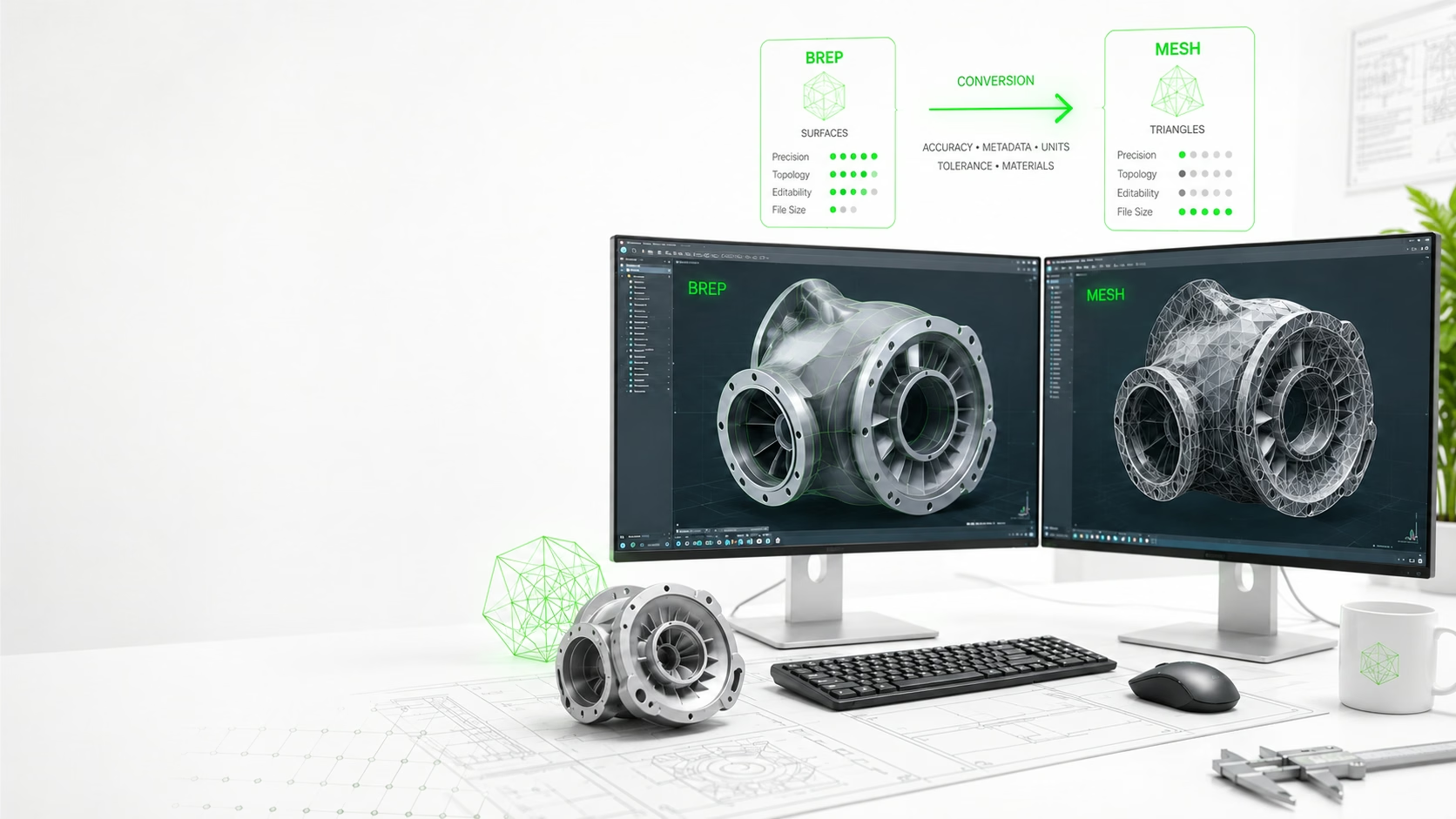
A mesh represents a 3D model using vertices, edges, and faces, usually triangles. It is excellent for visualization, 3D printing, game engines, web viewers, and fast geometric display. STL, OBJ, glTF, and many real-time formats are commonly mesh-oriented.
BREP, or boundary representation, stores analytic CAD surfaces, curves, topology, trims, and solid definitions. STEP, IGES, native CAD formats, and many manufacturing workflows depend on this richer representation because it supports precision editing, feature reconstruction, measurements, and downstream CAM or PLM processes.
Representation Comparison
One Model, Two Very Different Data Structures
Conversion Strategy
Why Conversion Quality Depends on the Target Workflow
A visually correct mesh may still be unsuitable for engineering edits if the receiving team needs true surfaces or solids. Likewise, a heavy BREP model may be unnecessary for a web viewer where performance and file size matter more than editable CAD topology.
The right conversion strategy should be selected by workflow: visualization, manufacturing, reverse engineering, QA comparison, data extraction, or archival. Each path has different expectations for accuracy, metadata, hierarchy, materials, and file size.
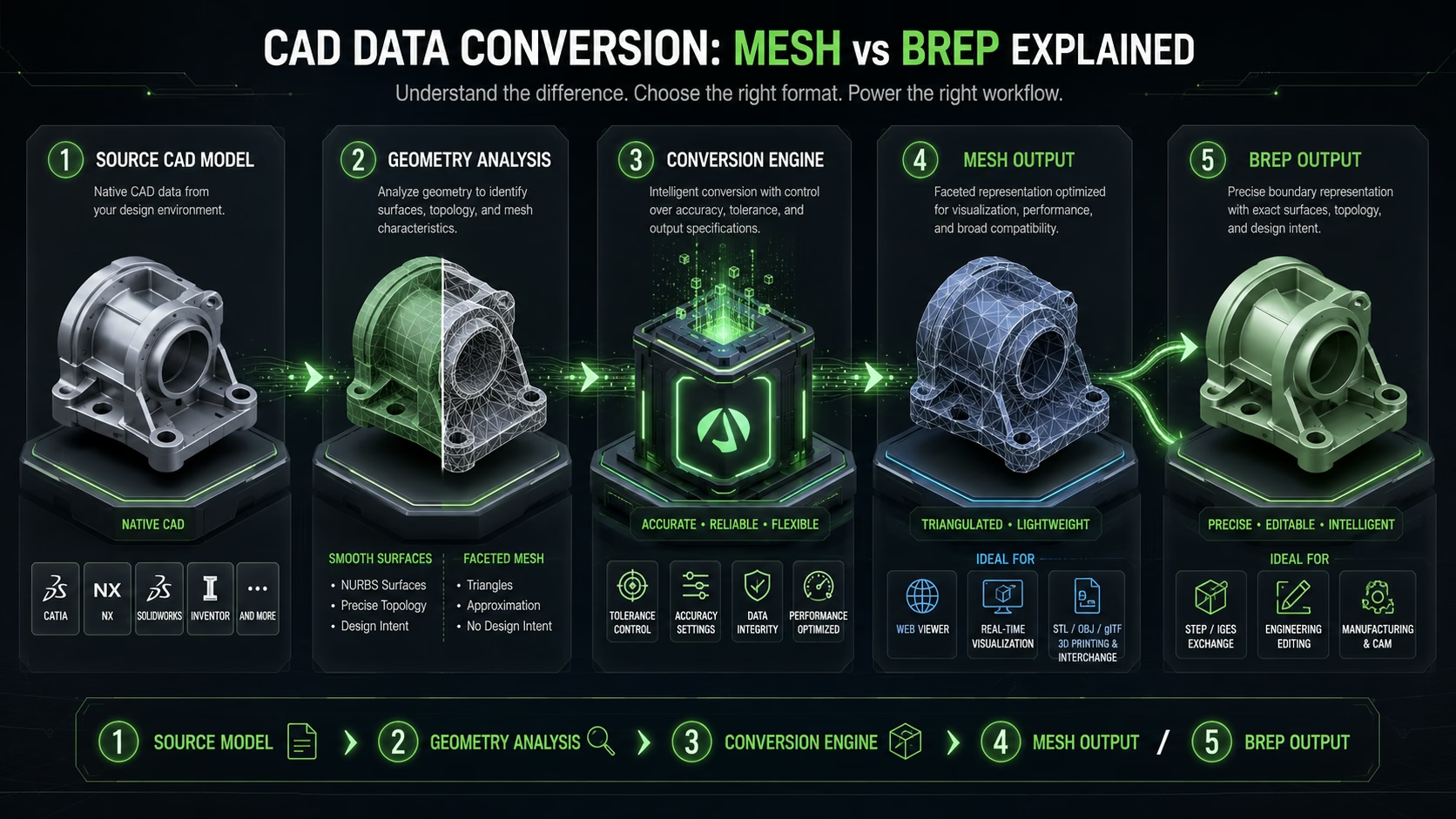
Inspect the Source
Identify the source format, units, model hierarchy, geometry type, materials, metadata, and assembly structure.
Define the Target Use
Choose whether the output is intended for visualization, manufacturing, editing, comparison, archiving, or interchange.
Set Conversion Rules
Control tolerance, tessellation quality, surface handling, normals, hierarchy, naming, materials, and metadata mapping.
Convert & Validate
Run the conversion and verify geometry completeness, units, orientation, file size, topology, and expected properties.
Deliver the Right Output
Publish a lightweight mesh, a precise BREP, or both—based on the downstream engineering requirement.
Output Selection
Choose the Format Around the Real Delivery Need
Visualization & Web
Create lightweight mesh outputs for real-time viewers, browser applications, AR/VR, and design review.
Manufacturing & CAM
Preserve precise BREP geometry for machining, tooling, measurement, and downstream manufacturing workflows.
Reverse Engineering
Convert scans or polygonal geometry into controlled surfaces when the receiving workflow requires editable CAD data.
Engineering Exchange
Move geometry, hierarchy, units, materials, metadata, and identifiers between CAD, PLM, and conversion systems.
Engineering Partner
Where Cadster Helps
Cadster Technologies builds CAD conversion pipelines, 3D viewers, mesh processing tools, and engineering data workflows. We help teams choose and implement conversion paths that preserve the information required by their real downstream process.