


Interoperability
Why IFC Matters in BIM Automation
BIM projects rarely stay inside one application. Architects, structural engineers, MEP teams, contractors, quantity surveyors, and facility teams often use different authoring, coordination, analysis, and delivery tools. Each platform stores geometry and engineering information differently, which makes reliable exchange difficult when the workflow depends only on native files.
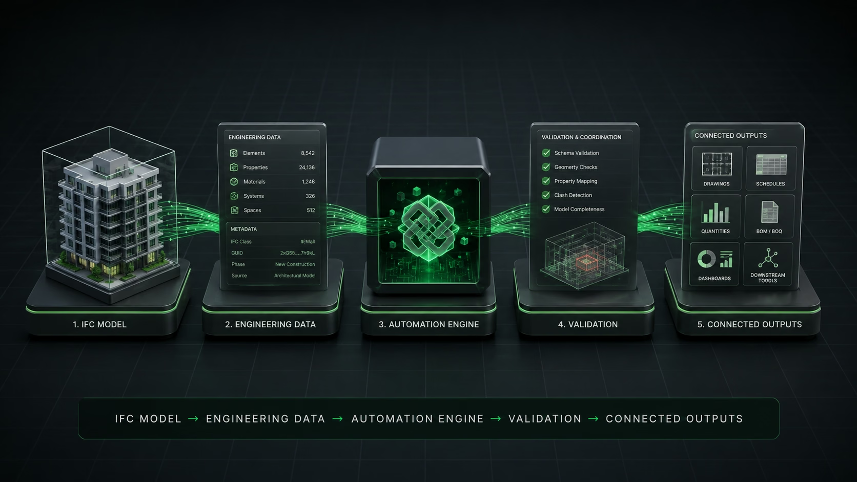
IFC provides a neutral and structured way to describe building elements, spatial hierarchy, relationships, properties, quantities, materials, systems, and classifications. In an automated workflow, IFC becomes more than an export format: it becomes a consistent data layer that software can inspect, validate, transform, compare, and connect to downstream systems.
Connected Engineering Data
How Engineering Data Moves Across Tools
The flow normally begins in discipline-specific authoring tools. Those models are exported or converted into IFC using agreed coordinates, classifications, property sets, naming rules, and model scope. An automation service can then read the IFC structure, identify each element, collect its properties and quantities, and preserve the relationship between geometry and metadata.
Once the data is structured, the same pipeline can create quantity reports, populate databases, validate project standards, prepare web-viewer data, detect missing information, compare model versions, and publish selected information to project dashboards or digital-twin platforms. This reduces repeated manual exports and helps teams use the same controlled engineering information across more than one application.
Common Use Cases
Where IFC Automation Creates Value
Model Exchange
Move coordinated architectural, structural, civil, and MEP information between authoring and review tools.
Data Extraction
Read elements, properties, quantities, materials, systems, spaces, classifications, and project hierarchy.
Validation
Check schema quality, required properties, geometry, naming, model completeness, and coordination rules.
Connected Workflows
Feed IFC data into viewers, dashboards, quantity tools, digital twins, databases, and internal applications.
Delivery Method
Typical IFC Automation Workflow
A dependable IFC workflow starts with clear exchange requirements. The team should define which disciplines are included, which IFC version is required, how coordinates and units are handled, which properties are mandatory, and what the receiving application expects. These rules should be tested with representative models before the pipeline is used on a complete project.
For digital-twin platforms, the automation layer often needs to connect authoring models with browser-based viewers, databases, permissions, project dashboards, and operational systems. This requires both BIM knowledge and software engineering discipline, including logging, validation, version control, failure recovery, and repeatable deployment.
Prepare Source Models
Confirm model coordinates, discipline ownership, export scope, classifications, naming, and required property sets.
Export & Normalize IFC
Generate a controlled IFC file and normalize versions, units, identifiers, object types, and project structure.
Extract Engineering Data
Read spatial hierarchy, geometry, quantities, materials, systems, metadata, relationships, and element properties.
Validate & Coordinate
Run automated checks for model completeness, mapping rules, required data, geometry quality, and coordination issues.
Deliver Connected Outputs
Publish drawings, schedules, quantities, reports, dashboards, web viewers, or downstream digital-twin data.
Engineering Partner
Where Cadster Helps
Cadster Technologies develops BIM automation and 3D visualization systems for teams that need reliable model processing, custom Revit workflows, IFC pipelines, and engineering data extraction. Our focus is to keep geometry, metadata, and business workflows connected.